Archive for December, 2009

Motor Power Transfer Design Update!

Chris needed to remove the clutch and take it home to 3d model it.  He found out, through closer examination that a shaft can be threaded into the clutch and secured with a bolt.  The new design reduces the amount of manufacturing and install time.  This design was also a lot stronger and far less costly.  He also determined that a support would need to be created to keep the shaft from breaking at the threaded end.  The 3d models can be seen below.

-Anthony

Here’s a picture of how it will all come together!

Leave a comment »

Miscellaneous 3d Models

We spent a bunch of time on our 3d Pro/E models (maybe a little too much).  Anyways, we think they look cool so check them out!

-Anthony

Leave a comment »

Throttle Control

We decided that we will use the electric motor as an accelerator assist.  This will help reduce the amount of time required to accelerate the cart to cruising speed.  When we hit full throttle on the gas pedal (cruising speed), the full throttle switch will be activated, opening the circuit.  This will shut the motor off and allow for full gas operation there on.  From the tests we found that the most inefficient fuel economy comes from when the cart goes from zero to cruise speed.  Here is a 3d model of the potentiometer/throttle cable assembly.

-Anthony

Leave a comment »

Electronic Wiring

Jason devised an electrical system that would put controlling all of the different drive options into 1 three-way toggle switch.  His electrical schematic can be seen below.

-Anthony

Leave a comment »

Motor Mount Material Thickness Selection

We ran simulations with the applied loads to find out which thickness of aluminum we needed.  The ‘sensitivity’ plot is seen below.

-Anthony

Leave a comment »

Kit Design

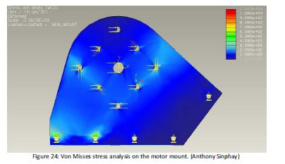
Here is our preliminary design for the motor mount. It will be bolted to the inside cart frame.  It will be made from ½ inch aluminum plate. The Finite Element Analysis says that this design will be able to support the exerted torque.

-Anthony

Motor Mount FEA

Motor Mount FEA

Here is what we plan on the motor mount and motor interface to look like

Here is how we plan on laying out our batteries.  We will have two deep cycle lead batteries in the rear trunk and one in the front console.

We plan on designing an interface to attach to the driven pulley to transfer the motor power to the driven clutch.

Leave a comment »

Ouch!

After Chris took the driven clutch home and took it apart, he realized it was going to be pretty hard to reassemble by himself.  The reassembly took pressing the clutch together, turning the spring and placing on a slip ring.  Stephen is in charge of putting the slip ring on once Chris presses it together and I turn it.  Stephen ends up shooting the slip ring into my hand leaving a pretty nice welt.  Good thing we all were wearing eye protection!

-Anthony

Leave a comment »